Sample Structured Home Wiring Projects
I have 2 projects plans from different homes that I have built. In the first plan I made a simple mock-up of the home layout and drew the lines for each wire. As you can see below, this overcomplicated the diagram. Please see the Wiring Plan Guide for more information or if you don't understand some of the examples below.
The second plan is cleaner since doesn't show the wires themselves. Instead, every wall plate is assigned a letter. The boxes on the right side of the diagram show what wires are available at that plate. Every wire in the basement is labeled with stickers to indicate what wall plate it connects to and what position it is in the plate. Ex: A coax cable with F5 label is the 5th coax cable on plate F. I also originally labeled the wires in the electrical boxes. This work was done before there was any dry-wall so the wall plates were added weeks after the original wiring was done. I also included the pin colors for the phone and Internet cables in the diagram so I knew how they were wired. For the Internet wire I used the less common EIA/TIA 568-A standard (instead of B) because it matches the phone colors for the inner 4 pins.
Click image for a larger view
This time I was more consistent in what I wired for each wall plate. Most of the time I used 4 port wall plates with 2 coaxial cable jacks, 1 cat-5 Internet jack, and 1 phone jack wired with cat-5 so it can be upgraded in the future. As you can see on the diagram, 10 different wall plates use this configuration.
Similar to the first plan, each bedroom has 2 wall plates at opposite ends. Each plate uses the standard 2 coax, 1 Internet and 1 phone setup.
The Master Bedroom has some jacks in odd locations. These were installed by the builder. Most of my work was behind the Armoire with the bed/bath speakers jacks again and another plate with the standard 2 coax, 1 Internet, & 1 phone jack.
I did a lot more in-ceiling speakers with this home. Trying to do ceiling speakers on the first floor is almost impossible once the drywall is installed, so I figured I should just wire everything. The Living Room, Dining Room, and Morning Room got in-ceiling speakers, and the Family Room and Study both got 2 pair of in wall speakers for surround sound. Like the first plan, most of the speaker wires terminated behind the entertainment center. I planned for a separate sound system in the Study, so the 4 Study speakers terminated in the corner of that room.
I still wanted to share audio/video between the Study and Family Room so I ran some wires directly between these 2 rooms. I wasn't sure what I needed, so I ran a little of everything. 3 component cables (made of coax but terminated with RCA component connectors) for Left/Right audio and video, Coax for Audio/Video, S-Video, Internet, and a VGA cable - which if done today would be HDMI. The component cables, S-Video, and VGA cable all have limits on how long they can be run so it wasn't practical to run these wires to the central location in the basement.
There are many more jacks behind the entertainment center besides the speaker connections and wires to the Study. There are 6 coax cables, 2 Internet and 2 phone jacks. This was absolute overkill but I wanted to ensure that I would never be short on connections. A dual-tuner TiVo uses 2 coax connections. If I ever get a HDTV antenna, that will take a 3rd. This time I used coax cable to run the audio/video signal from the computer to the Family Room so I can use the TV to watch movies off the computer. A 5th coax wire could be used to takes the output from the satellite receiver/TiVo and run it to another room. I figured 6 cables would be more than I would ever need.
The Morning Room and Study also got the standard 2 coax, 1 Internet and 1 phone setup.
The areas marked X and W are the kitchen island and counter top. These were wired after I closed. I didn't want to cut into the island before the house belonged to me. These both have an Internet and phone jacks. Like the previous plan, the idea here was for connecting laptops to the Internet.
This time the alarm system includes door sensors that chime when the doors are opened and closed. I wired the panels and motion detectors before drywall was installed, but I waited until after closing to do the doors. I didn't want to drill into the doors and possibly void the warranty before I even owned the home.
Wiring Panel
This is the wiring panel in the basement. As you can see, everything is well labeled and organized. I didn't want to repeat the mistakes I made in the first home.
Click image for a larger view
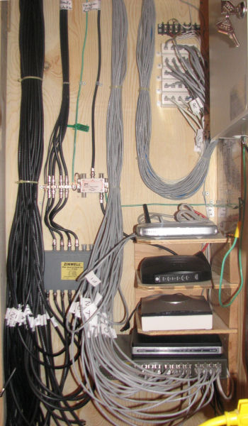
The panel is actually 2 boards in the a corner of the basement near the electrical box. If you click on the image for the larger version, you can see that everything is labeled and zip tied for a clean look. The boards are standard 2'x4' plywood that you can get from any hardware store. They are mounted to 2"x4"'s that are screwed directly into the concrete. From left to right the panels contain:
- Coax cable to the different rooms - most of these are not connected, 4 are connected to the satellite input and some are connected to each other so that different rooms can share the same signal.
- Incoming coax from the satellite dish - this is a triple LNB dish with four outputs so I didn't need a multiplexer to split the signal. 2 outputs go to the Master Bedroom and 2 go to the Family Room.
- Ground wire connected to the copper pipe - this is used to ground all the incoming coax cable lines and also is the ground for the alarm panel.
- Incoming cable feed - not in use but wired so that the cable company wouldn't need to mess with my panel in the future. This coax wire was placed furthest to the right because the incoming cable could also be used for Internet access.
- Internet cables to the different rooms - most of these are not connected, the rest are connected to the network routers. The top box in the stack is a wireless network router, the second is the DSL modem. The other two are straight network routers.
- Phone cables to the different rooms - most of this wire is Cat-5 Internet cable allowing for future upgrades.
- Incoming phone line - the phone feed is split using a DSL splitter into a DSL line and phone line. If you use DSL for Internet access, every phone line needs a DSL filter. By putting it in the basement right off the main feed I only need one filter for the whole house. The DSL line goes to the DSL modem. The phone line splits into a bank of phone jacks.
- Alarm Panel - The wires for the motion detector, door sensors, keypads, and horn enter the top of the alarm box. The power goes in the bottom. The box is locked and contains a battery backup.
- Power - The electrical panel is just to the right of this picture, but far enough away so that it wont cause any interference. The builder installed an outlet right next to the electrical box, so getting power to the routers and alarm was easy. I used a power strip with gaps between the sockets that was designed for use with power transformers.
These 2 pictures are of other areas in the basement. The builder ran most of the power wire around the edges of the home, so I ran my wire down the middle of the house along one of the I-beams. The other picture shows the wires going up through the first floor behind the entertainment center. Some of the wires run to the basement panel, and others go right back up to the Study. The coil of speaker wire is for speakers I want to eventually install in the basement when it is finished with the shared upstairs amplifier. By adding the wire now, I don't need to try to fish it through the wall later.